
What the Line Includes
The ZK oily sludge treatment system is the process line around the oil sludge centrifuge. Feed is received, heated and chemically conditioned, then separated in a 3-phase bowl into light phase (oil), heavy phase (water) and solids. A disc-stack separator can polish the oil phase. A vertical dryer is added when the cake needs further moisture reduction. LWF explosion-proof builds are used in Zone 1 or Zone 2.
3-Phase Decanter
LWS 3-phase bowl for oil, water and solids; LWF explosion-proof build for hazardous areas
Feed Conditioning
Heating typically 70–85°C, demulsifier, and polymer when fine solids need flocculation
Oil-Phase Polishing
Optional disc-stack centrifuge on the oil phase after the decanter
Layout
Skid-mounted or vehicle-mounted arrangement with PLC control

Line Equipment
3-Phase Decanter
- Machine: Oil sludge centrifuge (LWS / LWF)
- Bowl range: LWS250 ~ LWS650
- Hydraulic envelope: 1 ~ 30 m³/h on low-viscosity feed; oil sludge is sized from the feed package
- Duty: Continuous oil / water / solids split
Disc-Stack Separator
- Role: Polishes the oil phase after the 3-phase decanter
- Machine: Disc stack centrifuge
- Feed: Light phase from the decanter
- Duty: Fine solids and residual water in the oil
Control
- Drives: Main and scroll VFDs on the decanter
- Automation: PLC with HMI
- Integration: DCS interface where specified
- Hazardous area: Ex d motors and casing nitrogen inerting on LWF
Auxiliaries
- Heating: Steam or electric heating tank
- Chemicals: Demulsifier and polymer dosing
- Pumps: Feed pumps sized for viscous sludge
- Tanks: Oil, water and sludge buffer tanks
Oil Sludge Treatment Process
Receiving
Slop oil, tank-bottom sludge or lagoon sludge is transferred into the receiving tank
Conditioning
Heat to 70–85°C, add demulsifier, and add polymer when fine solids need flocculation
3-Phase Decanter
The 3-phase decanter discharges light phase (oil), heavy phase (water) and solids continuously
Oil Polishing
Where specified, a disc-stack separator removes residual water and fines from the oil phase
Water and Solids
The heavy phase goes to oily-water treatment. Cake is handled as discharged, or sent to a vertical dryer when further moisture reduction is required

Typical Duties
Refinery Slop Oil
Slop oil and API separator sludge from process units and tank farms.
- Slop oil recovery
- API separator sludge
- Turnaround cleaning waste
Tank-Bottom Sludge
Crude and fuel-oil tank bottoms with sand, rust and emulsified oil.
- Crude tank bottoms
- Fuel-oil tank bottoms
- Tank cleaning campaigns
Lagoon and Pit Sludge
Aged hydrocarbon sludge from ponds, pits and historical storage.
- Lagoon recovery
- Pit sludge
- Site cleanup feeds
Oilfield Tank and Pit Waste
Tank bottoms, wash sludge and pit sludge at production sites. LWF is specified where the area is Zone 1 or Zone 2.
- Production tank bottoms
- Wash and drain sludge
- Pit sludge
Drilling-mud solids control is a two-phase duty on the oilfield centrifuge, not this 3-phase oil sludge line.
Selected Installations
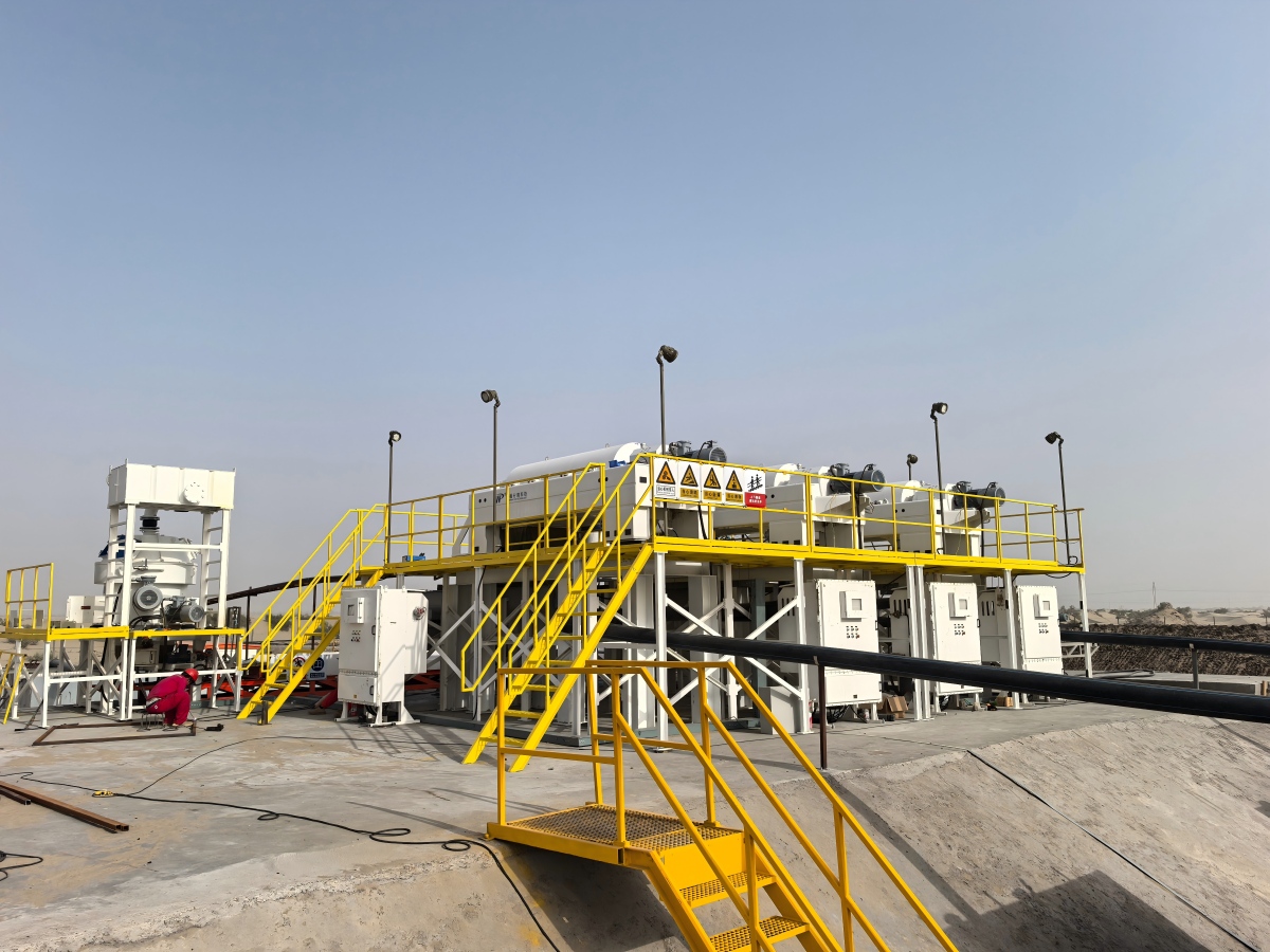
Three LWS650×2650B Decanters for an Environmental Company
Duty: Continuous oil / water / solids split on oily sludge, then solids drying
Scope: Three LWS650×2650B three-phase decanters and one dual-drive vertical dryer, skid-mounted
View InstallationTank-Bottom Sludge with LWS250×1025C
Duty: Tank-bottom sludge from crude and fuel-oil storage tanks
Scope: One LWS250×1025C three-phase decanter and one polymer dosing unit
View Installation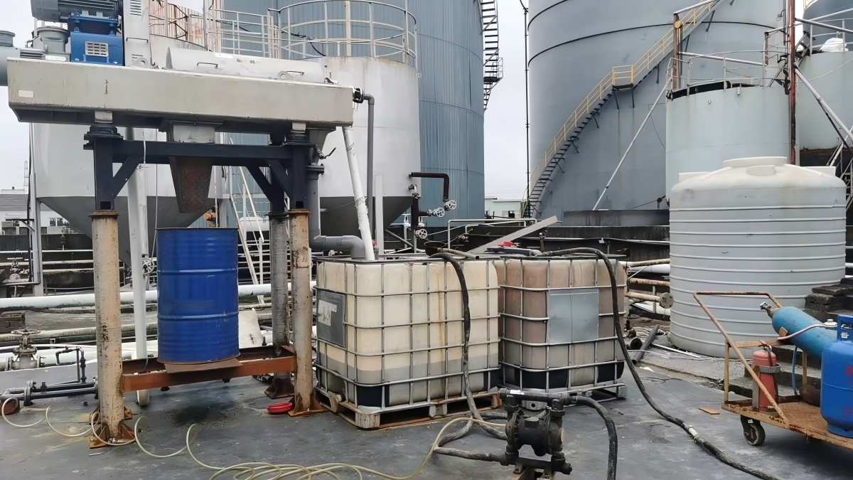
Decanter Features on the Line
Main and Scroll VFDs
Independent bowl-speed and differential-speed control. Bowl speed sets G-force; differential speed controls solids conveying. The oil-water interface is set by the weirs.
Shared DC Bus
On dual-drive machines a shared DC bus between main and scroll drives returns regenerated energy from the scroll motor.
Weir Discs and Paring Disc
Dam plates set pond depth and the oil-water interface with the bowl stopped. Selected machines add a paring disc or impeller for pressurized liquid discharge.
Tungsten Carbide Wear Parts
Replaceable tiles on the scroll flights and carbide or ceramic inserts at the solids discharge ports.
Duplex Bowl
Centrifugally cast duplex stainless steel (SAF 2205 or SAF 2304) or 316L for chloride-bearing hydrocarbon sludge.
LWF Nitrogen Inerting
On hazardous-area LWF builds the casing is purged with nitrogen. Oxygen sensors trip the machine if oxygen exceeds the setpoint.
Oily Sludge Treatment Line FAQs
A standalone oil sludge centrifuge is specified when the site already has tanks, heating and pumps. The full line is specified when receiving, heating, chemical dosing, the 3-phase decanter, oil-phase polishing and cake handling must be supplied together.
The light phase (oil) is collected and, where specified, polished in a disc-stack separator. The heavy phase (water) goes to oily-water treatment. Solids leave the bowl as cake; a vertical dryer is added only when further moisture reduction is required for handling or disposal.
Send sludge type (slop oil, tank-bottom or lagoon), oil-water-solids split, temperature, required feed rate and hazardous-area class (Zone 1/2 or safe area). ZK sizes heating, chemical dosing, LWS or LWF bowl and any disc-stack or dryer from that package.
Request a Treatment-Line Quote
Send sludge type, oil-water-solids split, temperature, feed rate and hazardous-area class.
Request a Quote