
3-Phase Decanter for Slop Oil and Tank-Bottom Sludge
The ZK oil sludge centrifuge is an LWS 3-phase decanter for hydrocarbon waste. Inside the rotating bowl the feed separates by density into light phase (oil), heavy phase (water) and solids. For Zone 1 or Zone 2 the machine is built as LWF: Ex d motors and nitrogen inerting of the casing, as specified. Wear zones use tungsten carbide. The bowl is centrifugally cast from duplex stainless steel or 316L; the scroll is duplex or 316L. Heating, demulsification, tanks and pumps are supplied with the machine as the oily sludge treatment system.

Machine Configuration
3-Phase Discharge: Separate outlets for light phase (oil), heavy phase (water) and solids. Weir discs (dam plates) set pond depth and the oil-water interface. Selected machines add a paring disc or impeller to discharge one liquid under pressure.
Hazardous-Area Build: LWF series with Ex d IIB T4 or Ex d IIC T4 main and scroll-drive motors, as specified for Zone 1 or Zone 2, plus nitrogen inerting and oxygen monitoring of the casing.
Wear Protection: Replaceable tungsten carbide tiles on the scroll flights; tungsten carbide or ceramic inserts at the solids discharge ports.
Continuous Operation: VFD and PLC control of bowl speed and differential speed, with torque monitoring, for continuous duty.
Typical Duties
Drilling-mud solids control is a two-phase duty on the oilfield centrifuge.
Built for Hydrocarbon Waste Service
Oily sludge carries abrasive sand, chlorides and, on sour service, hydrogen sulfide, with a fluctuating oil-water-solids split, often in a hazardous area. LWS and LWF oil sludge centrifuges are built for that duty.
3-Phase Oil-Water-Solid Separation
Discharge paths: Solids settle against the bowl wall. The scroll conveyor moves them up the beach to the solids discharge ports. The heavy liquid (water) forms the outer liquid layer; the light liquid (oil) lies closer to the bowl axis. The two liquids leave through separate outlets at the liquid end.
Pond and interface: Weir discs (dam plates) set pond depth and the oil-water interface. Weir rings are changed with the bowl stopped. Selected machines add a paring disc or impeller to discharge one liquid under pressure.
Explosion-Proof Build (LWF)
Hazardous area: LWF machines use Ex d IIB T4 or Ex d IIC T4 explosion-protected main and scroll-drive motors, as specified for Zone 1 or Zone 2. ATEX or IECEx documentation is supplied to the project specification.
Nitrogen inerting: The casing is sealed and purged with nitrogen. Oxygen sensors monitor the casing atmosphere and trip the machine if oxygen exceeds the setpoint.
Tungsten Carbide Wear Protection
Duty: Tank-bottom and lagoon sludge often carry silica sand and grit. Refinery slop can also carry catalyst fines.
Protection: Scroll flights are armored with replaceable tungsten carbide tiles. Solids discharge ports use solid tungsten carbide or sintered ceramic inserts. The feed zone is hardened against slurry impact.
Duplex Stainless Steel Bowl and Scroll
Materials: Petrochemical sludge can contain chlorides, hydrogen sulfide (H2S) and varying pH. The bowl is centrifugally cast from duplex stainless steel (SAF 2205 or SAF 2304) or 316L. The scroll is duplex or 316L.
Duty: Duplex stainless steel resists stress-corrosion cracking and pitting in chloride-bearing hydrocarbon service.
LWF and LWS Specifications
LWS is the 3-phase bowl for oil-water-solid split in a safe area. LWF is the explosion-proof build of that duty for Zone 1 or Zone 2, as specified, with Ex d motors and nitrogen inerting. Model selection uses feed rate, oil-water-solids split, temperature, viscosity and the required oil and water quality, not hydraulic flow alone. Bowl diameters follow the LWS 3-phase range.
LWF Explosion-Proof 3-Phase Decanter (Zone 1/2 as specified)
| Model | Speed (rpm) | Max G (×g) | Main Motor (kW) | Scroll Motor (kW) | Hydraulic (m³/h) | Dimensions (mm) |
|---|---|---|---|---|---|---|
| LWF250×1025C | 5000 | 3500 | 11 | 4 | 1~3 | 2800×800×1150 |
| LWF350×1435C | 4000 | 3136 | 22 | 5.5 | 4~8 | 3800×1050×1200 |
| LWF450×1845C | 3400 | 2913 | 37 | 11 | 8~12 | 4800×1150×1450 |
| LWF520×2150C | 3200 | 2982 | 55 | 15 | 15~18 | 5400×1250×1600 |
| LWF580×2400C | 3000 | 2923 | 75 | 22 | 20~25 | 5900×1400×1700 |
| LWF650×2650C | 2800 | 2854 | 110 | 30 | 25~35 | 6500×1650×1800 |
LWS 3-Phase Decanter (Safe Area)
| Model | Speed (rpm) | Max G (×g) | Main Motor (kW) | Scroll Motor (kW) | Hydraulic (m³/h) | Dimensions (mm) |
|---|---|---|---|---|---|---|
| LWS250×1025C | 5000 | 3500 | 11 | 4 | 1~3 | 2600×800×1150 |
| LWS350×1435C | 4000 | 3136 | 22 | 5.5 | 3~5 | 3500×1280×1058 |
| LWS450×1845C | 3500 | 3087 | 30 | 11 | 6~12 | 4000×1350×1100 |
| LWS520×2150C | 3200 | 2982 | 45 | 15 | 10~15 | 4800×1540×1250 |
| LWS580×2400C | 3000 | 2948 | 55~75 | 18.5 | 15~20 | 4900×1705×1250 |
| LWS650×2600C | 2800 | 2854 | 75~90 | 22 | 20~30 | 5900×1865×1300 |
Hydraulic figures are for low-viscosity feed. Oil sludge is sized from feed rate, oil-water-solids split, temperature and viscosity.
Process Ahead of the Centrifuge
Oil sludge is typically heated to 70–85°C and treated with a demulsifier before the centrifuge. Heating lowers oil viscosity; demulsification breaks the emulsion so the 3-phase bowl can form stable oil and water layers. Polymer is added when fine solids need flocculation.

Selected Oil Sludge Installations
Selected installations show the confirmed model, count and duty.
Tank-Bottom Sludge with LWS250×1025C
An oil sludge treatment company specified one LWS250×1025C three-phase decanter and one polymer dosing unit for tank-bottom sludge from crude and fuel-oil storage tanks.
The line conditions the feed with polymer, then the 3-phase bowl discharges oil, heavy phase (water) and solids continuously.
View Installation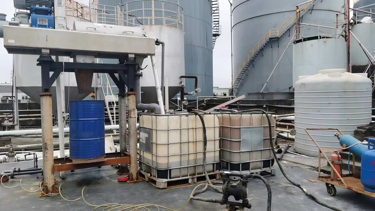
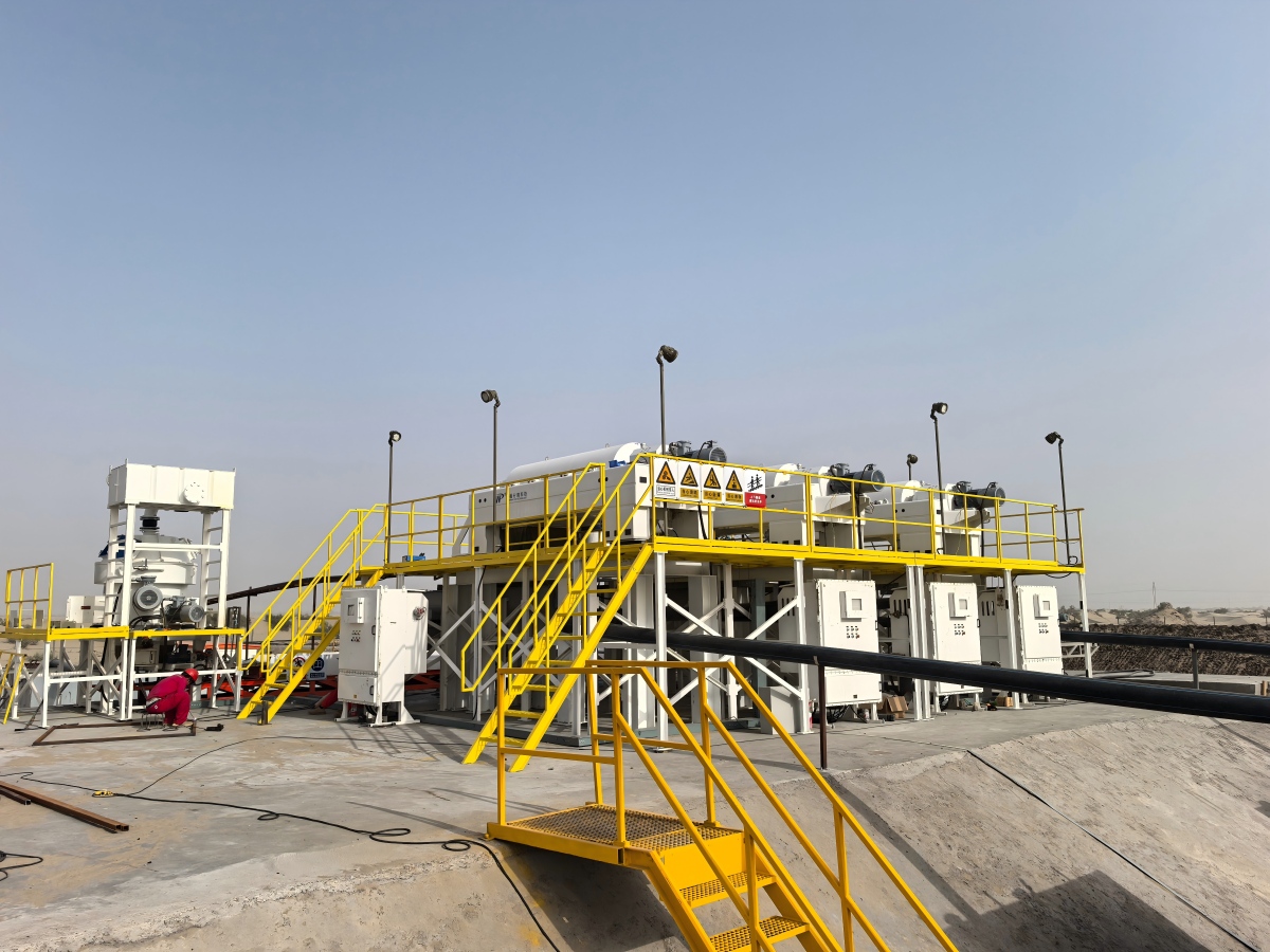
Three LWS650×2650B Decanters for an Environmental Company
An environmental service company installed three LWS650×2650B three-phase decanters and one dual-drive vertical dryer in a skid-mounted layout.
Three bowls run in parallel, each discharging oil, water and solids. Cake can be sent to the vertical dryer when further moisture reduction is required for handling or disposal.
View InstallationOil Sludge Centrifuge FAQs
A 3-phase decanter separates the feed by density inside the rotating bowl. Solids settle against the bowl wall and the scroll conveyor moves them up the beach to the solids discharge ports. Water (heavy phase) and oil (light phase) form concentric liquid layers. Weir discs set pond depth and the oil-water interface; they are changed with the bowl stopped. Selected machines add a paring disc or impeller to discharge one liquid under pressure.
Oil sludge releases volatile organic compounds and hydrocarbon vapour. Mixed with oxygen in the casing around a high-speed bowl, that atmosphere is an explosion hazard. Nitrogen inerting purges the casing and holds oxygen below the trip setpoint on Zone 1 or Zone 2 duty.
Tank-bottom and lagoon sludge carry silica sand and grit. Refinery slop can also carry catalyst fines. ZK fits replaceable tungsten carbide tiles on the scroll flights, tungsten carbide or ceramic inserts at the solids discharge ports, and hard-facing in the feed zone.
Send sludge type (slop oil, tank-bottom or lagoon), oil-water-solids split, temperature, required feed rate and hazardous-area class (Zone 1/2 or safe area). ZK sizes an LWS 3-phase bowl or an LWF explosion-proof build from that feed package.