
Decanter Centrifuge Working Principle
A decanter centrifuge operates on the principle that particles of different size and density separate under high-speed rotation. On industrial bowls this centrifugal acceleration is typically about 2,000–3,500 G, depending on bowl diameter and allowable speed. Separation also depends on viscosity, residence time and pond geometry — not on G-force alone.
Core Working Mechanism
The machine separates solids from liquids in a continuous process. The labeled schematic below is a 2-phase bowl. A 3-phase machine uses the same cake path and adds a second liquid outlet for the light phase.
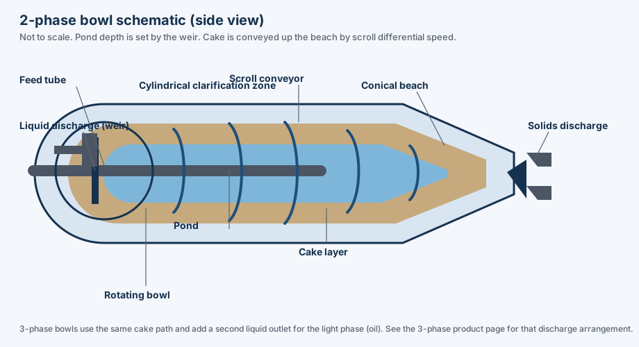
2-phase bowl schematic (side view, not to scale). Pond depth is set by the weir. Cake is conveyed up the beach by scroll differential speed.
1. Feed Introduction and Acceleration
The slurry (mixture of solids and liquids) is fed into the machine through an axial feed tube, which directs the material into the rotating bowl. The feed is accelerated by an internal accelerator, ensuring uniform distribution across the bowl's diameter. This initial acceleration is crucial for achieving consistent separation performance.
2. Separation by Centrifugal Force
As the bowl rotates (typically about 2,000–5,000 RPM, depending on diameter), centrifugal force of about 2,000–3,500 G pushes denser solids toward the bowl wall, forming a compacted cake layer. Liquids remain in the inner “pond” and flow toward the cylindrical-end discharge. Separation depends on particle size, density difference, viscosity, residence time, and G-force — not on G-force alone. Small high-speed bowls can reach about 3,500 G; large bowls run slower and often sit closer to 2,000 G. See the separation factor formula.
3. Solid Conveyance and Discharge
A helical scroll conveyor, rotating at a slightly different speed (differential speed, Δn) than the bowl, continuously moves the settled solids toward the conical beach and out the solids ports. Differential speed is set by a gearbox, hydraulic back drive, or dual-VFD drive — not by the bowl motor alone. Scroll pitch, tile material, and available torque determine how abrasive or sticky cakes are conveyed.
4. Liquid and Solids Discharge
- Solids: Compacted cake exits through ports at the conical end. Tungsten carbide tiles or hardfacing on the scroll flights resist abrasion; they do not by themselves control cake dryness.
- 2-phase liquid: Clarified centrate overflows adjustable weir plates (or a skimmer) at the cylindrical end. Weir diameter sets pond depth: a deeper pond usually gives clearer liquid and a wetter cake; a shallower pond gives a longer beach and drier cake, at the expense of centrate quality.
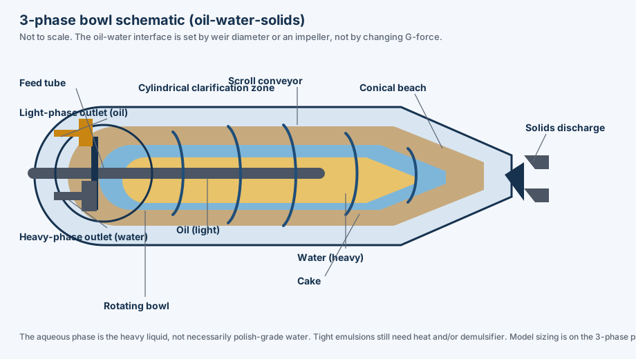
- 3-phase liquids: Light phase (oil) and heavy phase (water) leave through separate outlets. The oil–water interface is set by weir diameter or an impeller, not by running a different G-force.
2-Phase Decanter Centrifuge Working Principle
A 2-phase bowl separates solids from a single liquid phase. This is the usual configuration for sludge dewatering, industrial wastewater, starch processing, and mineral slurry clarification.

- Dewater Sludge: Remove water from municipal WAS or industrial wastewater sludge
- Clarify Liquids: Separate fine suspended solids from chemical or food process liquids
- Recover Solids: Extract valuable solid materials from liquid streams
- Reduce Disposal Volume: Minimize transport and landfill costs by concentrating cake solids
In 2-phase operation, slurry enters the bowl and separates into a compacted solid cake and a clarified liquid centrate. Model range, bowl diameter and a sized quotation are on the 2-phase decanter centrifuge product page.
3-Phase Decanter Centrifuge Working Principle
A 3-phase bowl separates three phases at once: two immiscible liquids (a light phase such as oil, and a heavy phase such as water) plus solids. Machine models and quotations are on the 3-phase decanter centrifuge product page; this section covers the bowl principle only.
This configuration is used for:
- Oil-Water-Sludge Separation: Refinery tank bottom sludge, lagoon cleaning, and oily sludge recovery
- Food & Edible Oil Extraction: Separating oil, water, and pomace in palm oil and olive oil processing
- Biofuel & Waste Lipid Recovery: Recovering fats and grease from food waste streams
- Chemical Processing: Handling multi-phase solvent-water-solid mixtures
The 3-phase bowl has two liquid outlets (adjustable weirs or an impeller) plus the solids ports, so recovered oil, the aqueous phase, and solids leave separately. The water phase is the heavy liquid, not necessarily polish-grade water; polish-grade clarity may still need a disc-stack separator downstream.
Key Components and Material Engineering
ZK SEPARATION's decanter centrifuges are engineered with high-quality materials to ensure durability and performance in harsh environments:
- Rotating Bowl: Constructed from duplex stainless steel (2205) or SS316L, offering superior corrosion resistance and strength. The bowl's conical section (beach angle) optimizes solid discharge dryness and can be customized for specific applications.
- Helical Scroll: Tungsten carbide tiles, PTA hardfacing, or ceramic inserts protect the flights. Service life depends on grit, slurry pH, and differential torque; carbide protection can exceed 15,000 hours in moderate-abrasion duty, while highly abrasive mineral slurries wear faster.
- Back Drive: A mechanical gearbox, hydraulic back drive, or dual VFD (bowl + scroll) sets differential speed and available conveyor torque. This is what controls solids residence time, not the bowl G-force.
- Bearings and Seals: Heavy-duty SKF or NSK bearings and double mechanical seals minimize maintenance and prevent leaks. The bearing system is designed to handle both radial and axial loads generated during operation.
- Weir Plates: Adjustable weir plates allow operators to fine-tune the separation process by controlling the pond depth and liquid discharge characteristics.
Performance Optimization Factors
To achieve optimal separation performance, ZK SEPARATION's decanters are configurable with adjustable parameters that can be optimized for specific applications:
- Bowl Speed: Higher RPM raises G-force with the square of speed (G ∝ RPM²) and helps capture slower-settling solids. Typical rated speeds are about 2,000–5,000 RPM depending on bowl diameter. Unflocculated cut size is often around 10 µm or larger; with polymer, flocculated fines well below that can be captured. A hard 5 µm clarification duty without flocculant is usually a disc-stack machine, not a decanter.
- Pond Depth: Adjusted via weir plates, deeper ponds yield clearer liquids, while shallower ponds produce drier solids. The optimal pond depth depends on the feed characteristics and desired separation results.
- Differential Speed: Controls the scroll's conveying rate, balancing solids dryness and throughput. Lower differential speeds result in drier solids but may reduce processing capacity.
- Feed Rate: The optimal feed rate depends on the material properties and desired separation efficiency. Over-feeding can reduce separation performance, while under-feeding reduces productivity.
- Temperature Control: For temperature-sensitive materials, heating or cooling systems can be integrated to optimize separation performance.
Industrial Applications
The same bowl family is used across several industries. The 2-phase or 3-phase choice follows the feed, not a brand preference:
Wastewater Treatment
In municipal and industrial wastewater treatment, decanter centrifuges are used for sludge dewatering and water clarification. The 2-phase decanter centrifuge working principle is particularly effective for:
- Municipal Sludge: Dewatering already-thickened sludge commonly cuts volume by about 70–90%, depending on feed DS% and cake dryness. Learn more about municipal sewage sludge treatment.
- Industrial Effluents: Treating wastewater from chemical, pharmaceutical, and food processing plants. Explore our industrial wastewater solutions.
- Mining Operations: Dewatering tailings and process water clarification. Discover our tailing dewatering applications.
Oil & Gas Industry
Oilfield and refining duties use both 2-phase and 3-phase bowls. They are not interchangeable:
- Drilling Mud Recycling (2-phase): Remove drilled solids from the liquid mud while retaining weighting agent (barite) where required. This is a solids-control decanter, not a 3-phase oil–water–solids machine. See our oilfield centrifuge solutions.
- Produced Water / Oily Sludge (2- or 3-phase): Remove oil and solids from produced water, or recover oil, water, and solids from tank-bottom and lagoon sludge. Learn about oily sludge treatment.
- Slop Oil Processing (typically 3-phase): Recover free oil from oil–water–solids mixtures. Tight emulsions still need heat and demulsifier. Explore oil sludge centrifuge technology.
Food & Beverage Processing
Food processing applications benefit from both 2-phase and 3-phase configurations:
- Olive Oil Extraction: 2-phase (oil + wet pomace) or 3-phase (oil, water, and pomace), depending on the mill. Discover our olive oil extraction systems.
- Starch Processing: 2-phase separation of starch granules from process water. Learn about starch extraction applications.
- Juice Clarification: Removing pulp and solids from fruit juices. Explore juice extraction solutions.
- Protein Recovery: Separating protein concentrates from process streams. See our protein extraction technology.
Chemical & Pharmaceutical
Chemical processing requires precise separation control and material compatibility:
- Catalyst Recovery: Separating valuable catalysts from reaction mixtures
- Precipitate Processing: Handling crystalline and amorphous precipitates
- Solvent Recovery: Recovering solvents from process streams
Operating Window and Service Factors
Installed power, throughput and materials are selected from feed data. The figures below are typical ranges for ZK industrial bowls, not a performance guarantee for a specific sludge or slurry:
- Energy Efficiency: Installed power depends on bowl size and solids loading — typically about 11 kW on compact machines to well over 130 kW on large bowls, plus the back-drive motor. Chemical use is often lower than on a filter press, but polymer is still required for most biological sludges.
- Continuous Operation: Indicative hydraulic throughput is typically about 1–100 m³/h depending on model and feed DS%; dilute slurries on the largest bowls can be higher. Dry-solids loading (kg DS/h) and scroll torque often limit capacity before volumetric flow does.
- Robust Design: Heavy-duty construction and corrosion-resistant materials for industrial duty. Standard process temperature is typically up to about 80°C; higher-temperature, low-ambient, and explosion-proof packages are selected by application.
- Customization: Tailored solutions for specific applications, including specialized configurations for 3-phase separation, high-temperature operation, and explosion-proof environments.
- Low Maintenance: Long service intervals and easy access to wear parts reduce operational costs and maximize equipment availability.
- Scalability: Standard bowls from 250 mm to 800 mm cover roughly 1 m³/h to about 100 m³/h hydraulic capacity; custom bowls up to 1000 mm are available when the application requires it.
Maintenance and Operational Checks
Service interval depends on grit, slurry pH, differential torque and lubrication. ZK SEPARATION publishes maintenance guidance with the machine; the checks below are typical, not a substitute for the manual:
Daily Operational Checks
- Vibration Monitoring: Check vibration levels to detect potential imbalance or bearing issues
- Temperature Monitoring: Monitor bearing and gearbox temperatures for signs of overheating
- Lubrication Levels: Ensure proper lubrication of bearings and gearboxes
- Performance Metrics: Record separation efficiency, solids dryness, and liquid clarity
Preventive Maintenance
- Regular Inspections: Schedule periodic inspections of critical components
- Wear Part Replacement: Replace tungsten carbide coatings and other wear parts according to manufacturer recommendations
- Cleaning Procedures: Implement regular cleaning protocols to prevent material buildup and corrosion
- Calibration: Calibrate control systems and sensors to ensure accurate operation
Troubleshooting Common Issues
Understanding common operational issues and their solutions helps maintain optimal performance:
- Poor Separation: May be caused by incorrect pond depth, excessive feed rate, or improper differential speed
- High Vibration: Often indicates imbalance, worn bearings, or material buildup
- Excessive Wear: Can result from abrasive materials, incorrect scroll design, or improper operation
- Liquid Carryover: May indicate incorrect weir plate settings or excessive feed rate
Selection Criteria for Decanter Centrifuges
Sizing starts from feed DS%, particle size, density difference, temperature and the required cake dryness or centrate quality. A trial or jar test is used when the sludge is biological or the emulsion is tight:
Application Requirements
- Material Properties: Particle size, density, abrasiveness, and temperature sensitivity
- Separation Goals: Required solids dryness, liquid clarity, and processing capacity
- Operating Environment: Temperature, humidity, and safety requirements
Technical Specifications
- Capacity Requirements: Feed rate and solids concentration
- Separation Efficiency: Particle size cut-off and separation factor requirements
- Control Systems: Level of automation and process control needed
Economic Considerations
- Capital Investment: Initial equipment cost and installation expenses
- Operating Costs: Energy consumption, maintenance, and consumables
- Return on Investment: Cost savings from improved separation efficiency
Frequently Asked Questions
How does a decanter centrifuge work?
Feed slurry is accelerated inside a rotating cylindrical-conical bowl. Centrifugal force settles denser solids against the bowl wall. A helical scroll, running at a small differential speed, conveys the cake to the solids ports. Clarified liquid overflows a weir on a 2-phase bowl, or leaves through separate light- and heavy-phase outlets on a 3-phase bowl.
What is the difference between a 2-phase and a 3-phase decanter?
A 2-phase decanter produces one cake and one liquid centrate. A 3-phase decanter also splits two immiscible liquids, such as oil and water. The oil–water interface is set by weir diameter or an impeller, not by changing G-force. If the process only needs solid-liquid split, a 2-phase bowl is the usual choice.
What do pond depth and differential speed control?
Weir diameter sets pond depth. A deeper pond usually gives clearer liquid and a wetter cake; a shallower pond lengthens the beach and tends to dry the cake. Differential speed (Δn) is set by a gearbox, hydraulic back drive, or dual VFD — not by the bowl motor alone. Lower Δn increases solids residence time but reduces conveying capacity.
Where are models and quotations listed?
This page is the working-principle article. Bowl diameter, hydraulic capacity and a sized quotation are on the decanter centrifuge product page, with separate pages for 2-phase and 3-phase bowls.
Conclusion
Whether the bowl is 2-phase or 3-phase, separation is set by G-force, pond depth, differential speed, and feed properties — not by any one of those parameters alone.
For model data and a sized quotation, use the industrial decanter centrifuge product page. For application-specific questions, contact the technical team with feed DS%, flow rate and the required cake dryness or centrate quality.